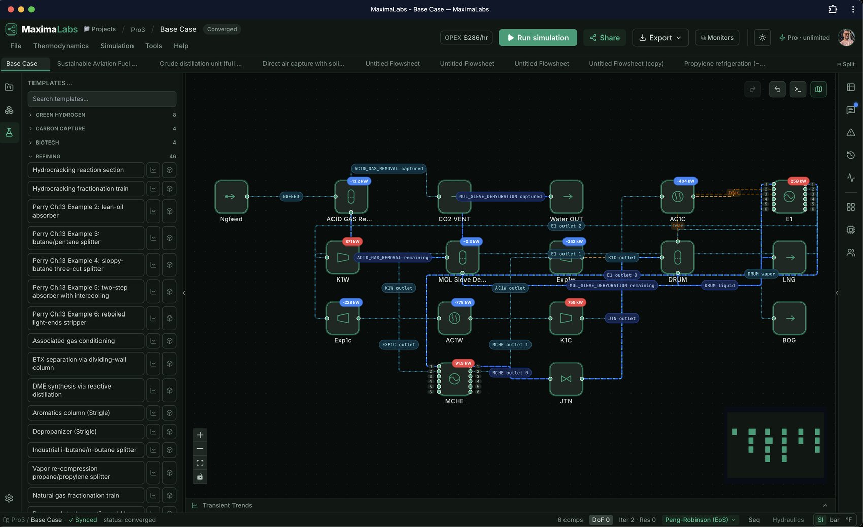
How to simulate h2 recovery from purge gas by gas-permeation membrane
A real technology gap this codebase had no unit op for at all: gas-phase membrane separation (the existing `membrane` op is liquid-phase reverse osmosis, not gas permeation). Built here as a new `gas_membrane` unit op -- solution-diffusion transport (real textbook model), solved as the coupled fixed point it actually is (both outlet compositions depend on every component's flux, which depends on both outlet compositions) via a proper Newton-type root-find rather than naive fixed-point substitution, which was tried first and found to genuinely oscillate for a stiff permeance*area product -- see the unit op's own module docstring. Demonstrates the textbook H2-recovery application: a high-pressure purge/off-gas (H2/CH4/N2, e.g. from an ammonia loop or hydroprocessing unit) crosses a polyimide-class membrane, H2 permeating far faster than the other species. Honesty note: the permeance values used are representative order-of-magnitude figures for a polyimide-class membrane's real H2/CH4/N2 selectivity pattern (H2 permeates markedly faster than either), not digits pinned to one specific cited membrane material/thickness -- disclosed as representative rather than presenting invented precision, the same posture used elsewhere in this codebase when an exact source isn't confidently pinnable. The single-stage recovery shown (~32% of the feed H2, at ~96% permeate purity) is a real, honest limitation of one membrane stage -- real plants cascade multiple stages for higher overall recovery, not modeled here.
- 1Open the ready-made model
Open the "H2 recovery from purge gas by gas-permeation membrane" model in the MaximaLabs workspace — no install, no license. It loads live on the canvas, ready to edit and run.
- 2Confirm the thermodynamics
This process is modeled with the PENG-ROBINSON property package over h2, methane, n2 — already selected, so the phase equilibrium and enthalpy are physically consistent from the first run.
- 3Review the flowsheet
The flowsheet chains Membrane. Every block is a real, solvable unit op you can reconfigure on the canvas.
- 4Run the simulation
Click Run. The deterministic solver converges the material and energy balances (recycles included) and fills the live stream table — the AI never invents a number.
- 5Read the results and iterate
Inspect the converged streams, tweak a spec, and re-run — or ask the AI copilot to explain a result or diagnose a failed solve in plain English.
- Thermodynamics
- PENG-ROBINSON
- Components
- h2, methane, n2
- Unit operations
- Membrane
Opens live on the canvas — free, no install.
Explore the model & flowsheetFrequently asked questions
- What does the H2 recovery from purge gas by gas-permeation membrane model simulate?
- A real technology gap this codebase had no unit op for at all: gas-phase membrane separation (the existing `membrane` op is liquid-phase reverse osmosis, not gas permeation). Built here as a new `gas_membrane` unit op -- solution-diffusion transport (real textbook model), solved as the coupled fixed point it actually is (both outlet compositions depend on every component's flux, which depends on both outlet compositions) via a proper Newton-type root-find rather than naive fixed-point substitution, which was tried first and found to genuinely oscillate for a stiff permeance*area product -- see the unit op's own module docstring. Demonstrates the textbook H2-recovery application: a high-pressure purge/off-gas (H2/CH4/N2, e.g. from an ammonia loop or hydroprocessing unit) crosses a polyimide-class membrane, H2 permeating far faster than the other species. Honesty note: the permeance values used are representative order-of-magnitude figures for a polyimide-class membrane's real H2/CH4/N2 selectivity pattern (H2 permeates markedly faster than either), not digits pinned to one specific cited membrane material/thickness -- disclosed as representative rather than presenting invented precision, the same posture used elsewhere in this codebase when an exact source isn't confidently pinnable. The single-stage recovery shown (~32% of the feed H2, at ~96% permeate purity) is a real, honest limitation of one membrane stage -- real plants cascade multiple stages for higher overall recovery, not modeled here.
- Which thermodynamic method does it use?
- The PENG-ROBINSON property package, over h2, methane, n2 — already selected. You can switch the method on the canvas before running.
- Which unit operations are in the flowsheet?
- It chains Membrane. Every block is a real, solvable unit operation you can reconfigure, add to, or remove.
- Do I need to install software or buy a license?
- No. H2 recovery from purge gas by gas-permeation membrane runs entirely in your browser on MaximaLabs — free, no install, no license. Open the model to load it live and run the deterministic solver.
More guides like this
Polymerization reactor comparison: CSTR cascade vs. tubular (PFR)
The same monomer feed, split 50/50 into two trains at equal total reactor volume: a 3-stage CSTR cascade (each stage blending its own new polymer with the MWD already carried by the stream from the stage before it) versus a single tubular (PFR) reactor. Both converge to a real, different Mn/Mw/PDI — the PFR reaches higher conversion at the same total volume, but its cumulative polydispersity is measurably broader than the cascade's, because chain length drifts continuously with conversion along the tube while each CSTR stage makes its own local production under one fixed monomer concentration. See the 'Polymerization Reactors' docs page for the full reasoning.
Helium liquefaction (Linde-Hampson cycle)
A Joule-Thomson liquefaction loop: helium is compressed, aftercooled, precooled well below its ~40-51 K JT-inversion temperature, then throttled through a valve into a flash drum that draws off liquid helium while the cold vapor recycles back to the compressor suction — the same JT-cycle physics as the platform's LNG/refrigeration loops, run on a fluid whose inversion curve makes precooling mandatory before the throttle can cool it at all.
Cement kiln calcination + CO2 liquefaction
Preheated limestone (CaCO3) enters an indirectly-heated rotary kiln that calcines it toward CaO, releasing a CO2-rich off-gas; the gas is knocked free of moisture, then compressed and cooled to liquefy the CO2 for transport/storage. Honesty notes: (1) this specific kiln model (rotary_kiln) heats via an indirect utility-temperature wall duty (an NTU model), not a simulated internal flame, so no combustion stoichiometry runs inside it here — real oxy-fuel combustion IS modeled elsewhere in this codebase (fired_heater's oxidant="oxy_co2" mode: near-pure-O2 combustion diluted by a recycled-CO2 stream instead of air's nitrogen), see allam-fetvedt-cycle for a real working example of it; (2) the calcination conversion shown (~21%) is the real, kinetically-limited result of this model's validated Arrhenius parameters at this residence time/temperature, not a claim of complete calcination — a real cement plant's preheater-tower-plus-kiln train achieves far higher calcination degree than one rotary-kiln unit alone models here; (3) CO2 must be compressed above roughly 5.2 atm before it can be liquefied by cooling at all (it has no liquid phase at 1 atm at any temperature), which the compressor stage here reflects.
NGL fractionation: single-shell Petlyuk dividing-wall column
A natural-gas-liquids cut (ethane / propane / n-butane) split into three on-spec products by ONE thermally-coupled dividing-wall column instead of two columns in series. This uses the native Petlyuk unit op: a prefractionator whose reflux and boilup are supplied by the main column (the single condenser + single reboiler), solved by an outer Wegstein loop that converges the bidirectional vapor/liquid coupling to self-consistency — the coupling legacy sequential-modular solvers approximate with two connected columns whose recycle fails to converge. Honesty note: the vapor-split and liquid-split ratios are specified inputs (not solved from tray hydraulics), and this is an outer-loop coupling of two rigorous MESH sub-solves, not a single monolithic Petlyuk MESH.
Ethanol–water distillation
An 8-stage column concentrating ethanol overhead toward the azeotrope (the headline demo).
Distributed pipeline cool-down (indexed equation model)
A hot gas cools along a buried pipeline — modeled as a custom unit op whose internals are a distributed 1-D indexed equation system, the gPROMS-style array + indexed-equation modeling capability solved by the sandboxed equation engine. Twenty axial segments compute the full temperature profile T[0..20] (the inlet drives the boundary T[0]; each segment loses heat toward the ground temperature); the outlet temperature is the end of that profile. Demonstrates writing a distributed model as one indexed template rather than 20 hand-written equations.