The AI-Native Process Simulator — From Flowsheet to Live Digital Twin
Build, solve, and auto-calibrate complex process simulations directly in your browser. A 10x faster workflow than desktop software or license-server delays.
No software installation or credit card required · Opens instantly in browser
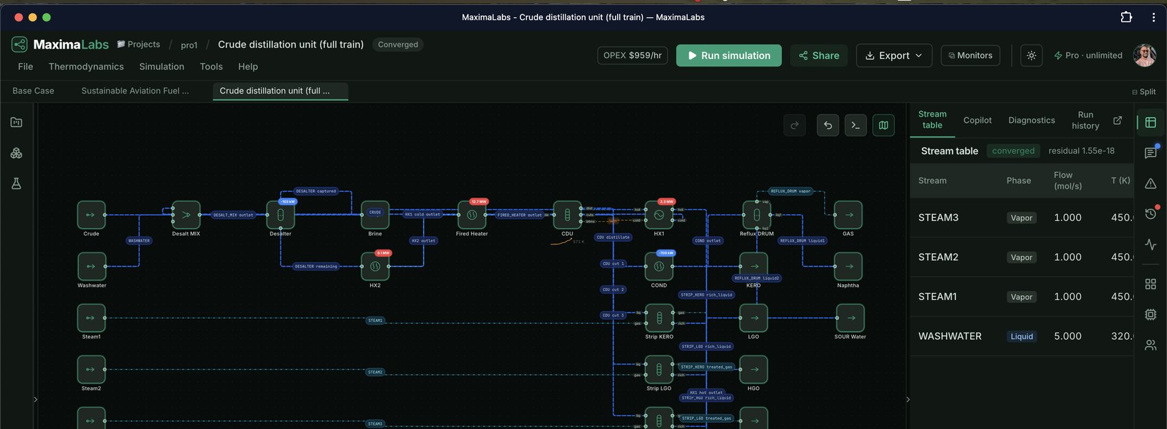
A real converged run — crude distillation, 6 components, Peng-Robinson.
Open a real model, not a demo video
Three production-shaped flowsheets from the library. Each opens live on the canvas — editable, solvable, with the equations behind every block.
Crude distillation (preset cuts)
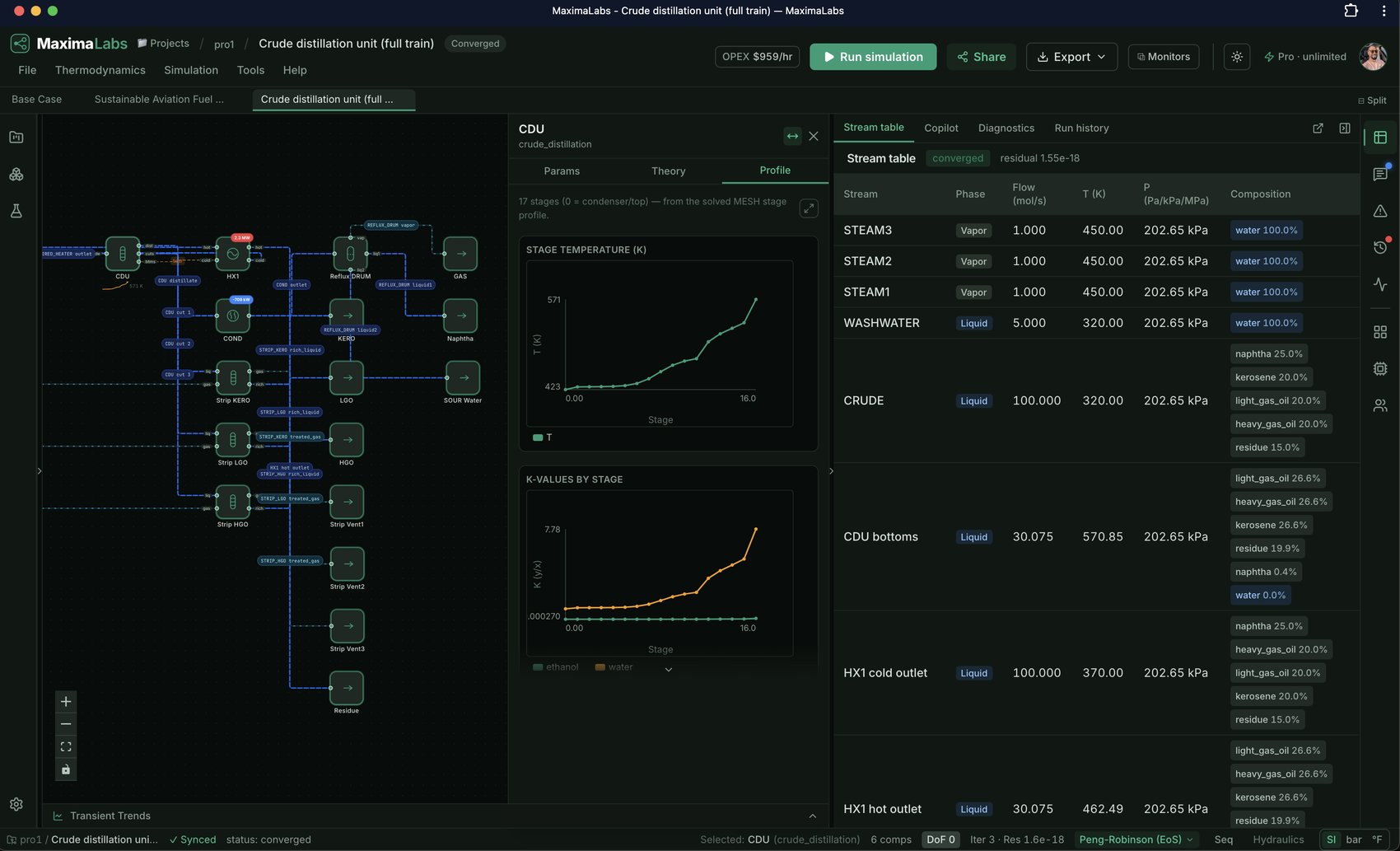
A rigorous 14-stage MESH column on Peng-Robinson, with per-stage temperature and K-value profiles.
10 MW PEM electrolyzer loop
A 10 MW PEM electrolyzer stack with its recirculation loop, solved end to end.
Solid-sorbent fluidized-bed DAC with compression heat recovery
Solid-sorbent direct air capture with compression heat recovery, across 14 blocks.
One platform covers the whole workflow — no export step between design and the live plant.
Build. Connect. Collaborate.
One platform covers the whole workflow — no export step between design and the live plant.
Describe the plant in plain English. The Copilot handles the flowsheet.
Generate flowsheets from plain English and get plain-English fixes for failed solves — not cryptic codes. Every governing equation stays open — column MESH, reactor rate laws, mass/energy residuals in real LaTeX — so engineers know it isn't a black box.
Stream real-time telemetry directly onto active flowsheet nodes.
Live OPC-UA, Modbus, EtherNet/IP, MQTT, or Sparkplug B tags flow onto the same flowsheet the simulator solved, with autoencoder soft-sensor anomaly detection — not a separate dashboard.
Paste an OPC-UA endpoint and hit Connect — your live plant, on the model.
Multi-cursor real-time editing & a native Python SDK.
Multiple engineers on one live flowsheet with cursors and presence, plus a zero-dependency `pip install flowsim-sdk` client or the =FLOWSIM.RUN() Excel add-in.
pip install flowsim-sdk

from flowsim.sdk import FlowSimClient
client = FlowSimClient("https://maximalabs.io")
sim = client.run_and_wait("demo", flowsheet)
print(client.streams(sim["id"]))Ask for a flowsheet. Get a solved one.
The AI proposes the flowsheet; the solver still computes every number.
Bring what you already have
Drop a P&ID or a datasheet and the AI reconstructs the flowsheet. Aspen .bkp and HYSYS .hsc files import deterministically — no AI in the loop.
Have an existing P&ID or equipment datasheet?
Drag a PDF datasheet or a P&ID image here — MaximaLabs reconstructs a live, editable, solvable flowsheet from it instead of you re-keying every stream and unit op by hand.
Reads stream tags and equipment types; you'll review and fix anything it couldn't confidently map before running it.
Built for real processes
Open any template and it loads straight onto the canvas — solved and ready to edit.
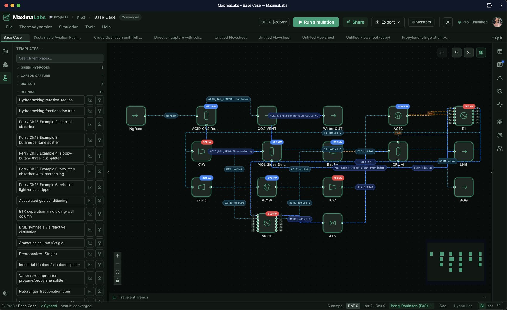
Search 90+ pre-built templates by industry or species — every one solved and ready to edit.
HYSYS was built for oil & gas. MaximaLabs ships the new-energy unit ops and workflows you actually need.
Why engineers switch
Zero install, anywhere
Open a browser and simulate. No license servers, no 2003-era desktop, no IT ticket.
Python-first & rigorous
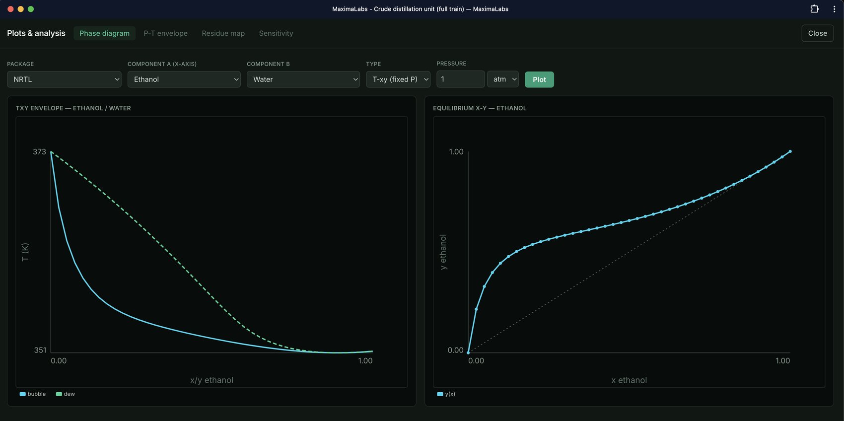
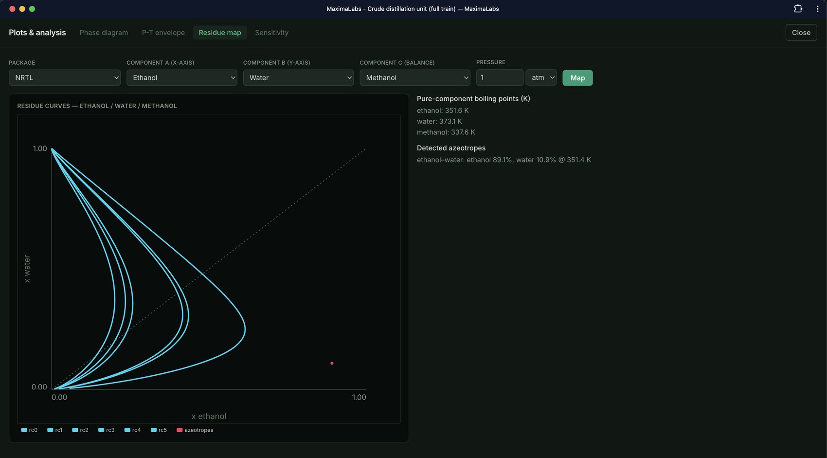
NumPy/SciPy/CoolProp under the hood, validated against published VLE data. A first-class Python API.
From screening to design deliverables
Instant capital cost, heat-exchanger rating, energy optimization & case studies, and safety checks (LEL/HAZOP, API 521 relief).
MaximaLabs vs. legacy desktop workflows
The same shift shows up across every dimension of the workflow, not just the sticker price.