Heat Transfer & Energy Integration
Almost every process spends most of its operating cost on heating and cooling. This chapter is the equipment that moves heat — heaters, coolers, and exchangers — and then the bigger idea that saves the money: making the hot streams heat the cold ones instead of paying for utilities twice.
6.1 Heaters and coolers
The simplest energy units add or remove a duty. You specify either the duty
- Duty — heat added (Q>0, a heater) or removed (Q<0, a cooler).
- Molar flow through the unit.
- Inlet and outlet molar enthalpy, from the active thermo package.
A heater takes
5 mol/s at
6.2 The heat exchanger
A heat exchanger couples two streams: a hot one giving up heat and a cold one taking it. No utility is consumed — the duty simply moves from one side to the other, so its energy balance is a pair of matched terms:
- Molar flow of the hot and cold streams.
- Molar enthalpy of each stream at its inlet and outlet — the duty that leaves the hot side exactly equals the duty that enters the cold side.
The example below is a crude-distillation train where the hot column products preheat the cold crude feed through a feed-effluent exchanger before it ever reaches a fired heater — recovered heat that would otherwise be paid for twice.
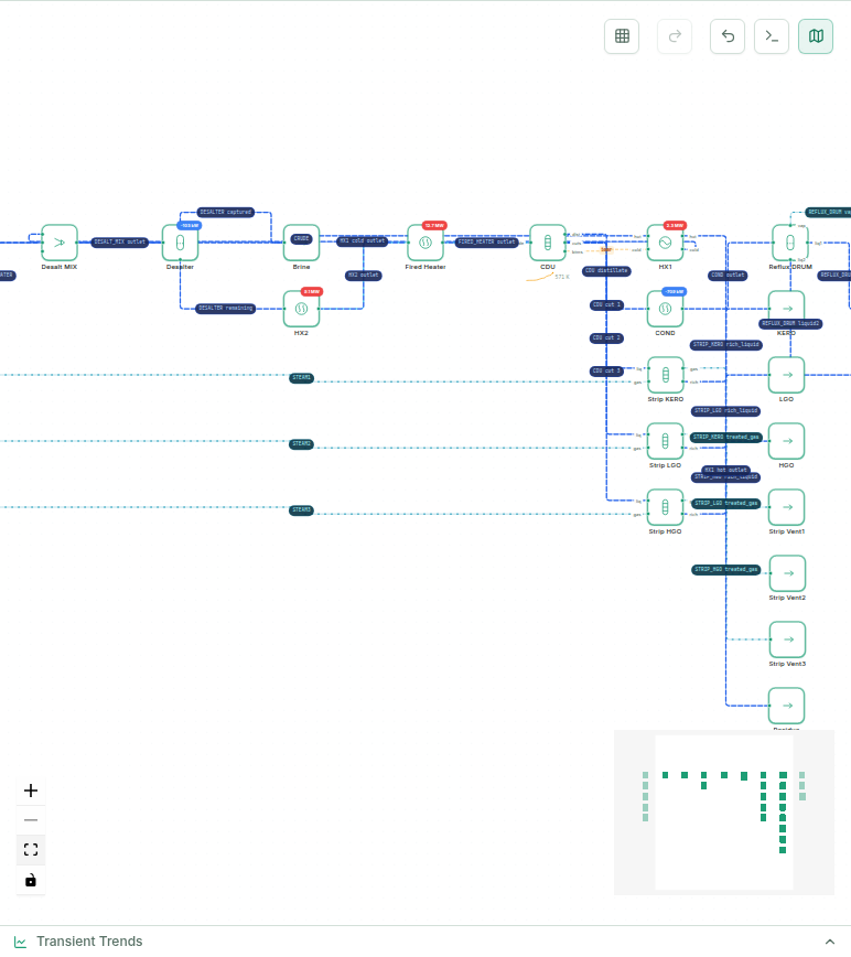
A heat-integrated crude train: the feed-effluent heat exchanger recovers heat from hot products into the cold feed before the fired heater — the exchanger consumes no utility, it just relocates duty.
6.3 Rating: how big must the exchanger be?
Knowing the duty isn't the same as knowing the exchanger will fit it. The transfer rate is set by the area
- Overall heat-transfer coefficient — how readily heat crosses the wall between the two fluids.
- Heat-transfer area.
- Log-mean temperature difference — the effective driving force averaged over the exchanger's length.
- Temperature difference between the two streams at each end of the exchanger.
- Correction factor (≤1) for a non-pure-counter-current geometry (below).
Counter-current terminals: hot 400 K→350 K, cold 300 K→340 K (illustrative):
- Hot-stream inlet and outlet temperature.
- Cold-stream inlet and outlet temperature.
- Cold-side thermal effectiveness — how much of the maximum possible temperature rise the cold stream actually achieves.
- Capacity-rate ratio — the hot-to-cold ratio of mass flow times specific heat.
Same terminals as the LMTD example above (hot 400→350 K, cold 300→340 K):
In practice
Rating asks: for a given geometry, is the available area enough for the required duty? MaximaLabs' HX design panel (an EDR-style rating) takes the duty, terminal temperatures, and shell/tube/baffle geometry and returns the overall
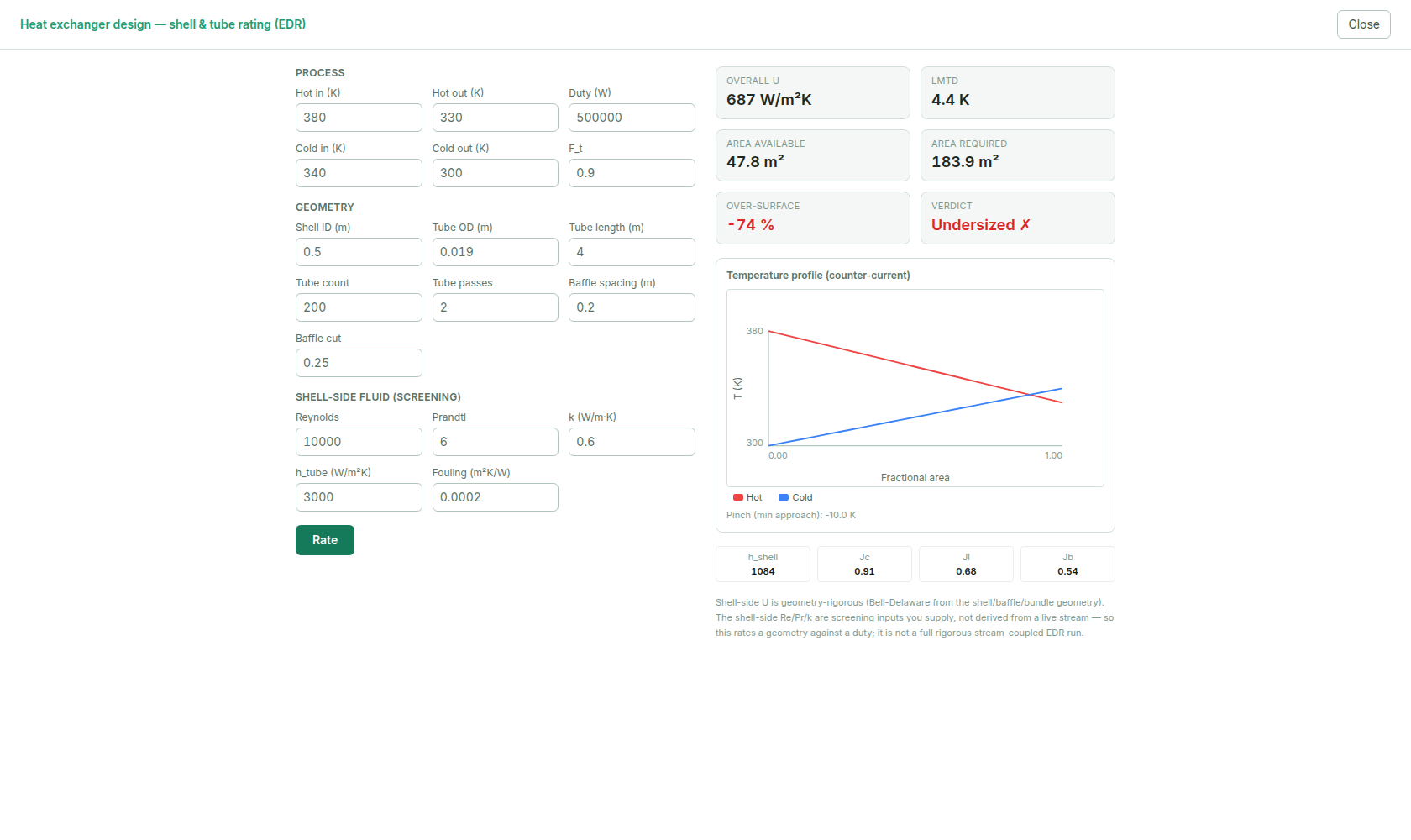
HX design (EDR): rate a geometry against a duty — U, LMTD, required vs. available area, the over-surface margin (✓ adequate / ✗ undersized), and the hot/cold temperature profile down the exchanger. Change geometry and re-rate.
6.4 Energy integration: the pinch
One exchanger recovers heat between two streams. A whole plant has many hot and cold streams, and the question becomes: what is the least heating and cooling utility this process could possibly need? That's pinch analysis. You combine all hot streams into a hot composite curve and all cold streams into a cold composite curve, slide them together until the closest approach equals a chosen
- Minimum hot and cold utility the process could reach with a perfectly integrated network — the target.
- The temperature where the hot and cold composite curves come closest (exactly \Delta T_min apart).
A symmetric two-stream case (hot 100 K→40 K, cold 30 K→90 K, both CP=1 W/K, ΔT_min=20 K) — reproduced from this codebase's own validation test:
The point where the curves touch is the pinch; it divides the process into a heat-deficit region above and a heat-surplus region below, and the golden rule — don't transfer heat across the pinch — is what unlocks the minimum-utility target. MaximaLabs runs the Linnhoff targeting over the solved flowsheet and reports the minimum hot/cold utilities and the savings left on the table versus the current design:
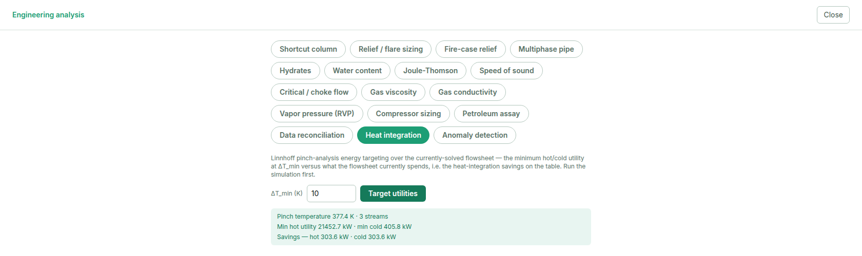
Pinch (Linnhoff) targeting over the solved crude train: the pinch temperature, the minimum hot and cold utility the process could use, and the utility savings still available — the number that justifies adding a heat exchanger.
6.5 From target to design: the heat-exchanger network
Targeting (§6.4) tells you the minimum utility a perfectly-integrated network could reach — but not which streams to match against which, or how many new exchangers to add. The pinch design method answers that with a grid diagram (hot streams left-to- right on top, cold streams below, the pinch drawn as a vertical line splitting the grid) and one governing rule: split the problem at the pinch and design each side separately, since no stream may legally cross it.
Immediately next to the pinch, a match is only feasible if it can carry the full duty without a temperature cross. That reduces to a heat-capacity-flow (
- Heat-capacity flow rate \dot m c_p — how much duty a stream gives up (or absorbs) per degree.
- The CP of the hot and cold stream in a candidate match — which one must be larger sets which side of the pinch the match is feasible on.
The tick-off heuristic then greedily matches streams pinch-outward: at each step, match the largest feasible pair, exhaust ("tick off") whichever stream runs out of duty first, and carry the other's remainder to the next match. Repeat until every stream is either fully matched against another process stream or left with a residual duty — which becomes the hot/cold utility this design actually needs. MaximaLabs runs exactly this algorithm over your solved flowsheet's real hot and cold streams and returns the match list, each exchanger's estimated area, and — honestly — a flag on any stream a stream-split would be needed to match (the one case tick-off alone can't resolve): open the same Energy panel's Network design tab (right beside the targeting view above) and it lists the proposed matches, each one's duty and estimated area, and the utility remaining after matching — the same streams §6.4 targeted, now actually assigned to exchangers.
This is screening-level, not detailed exchanger design — no stream-split optimization, no capital-cost weighting between candidate networks — but it's the real next step after a target: an actual list of exchangers to add, sized well enough to cost and specify.
6.6 Try it
- 1Open a heat-integrated example — the crude distillation train — and Run it.
- 2Click the feed-effluent heat exchanger and read its two-sided duty and the hot/cold terminal temperatures in the stream table.
- 3Open HX design (EDR) (right rail ▸ Analysis & reports), hit Rate, and read the LMTD, U, and required-vs-available area. Shrink the shell diameter and re-rate to watch the over-surface margin go negative (undersized).
- 4Open Engineering analysis ▸ Heat integration, set a , and click Target utilities to see the minimum-utility target and the savings against the current design.
- 5Switch to the Network design tab — same panel — to see the tick-off match list that actually reaches the target: which streams pair up, and what's left as genuine hot/cold utility.
Heat transfer is where a correct simulation turns into a cheaper plant: size the exchangers so they fit, then integrate them so the process heats itself. Next: turning a converged model into decisions — sensitivity, design specs, and optimization.
6.7 Exercises
Work each problem yourself first, then reveal the solution to check it. Where a problem says so, reproduce it live in MaximaLabs — the solver is the answer key.
- 1warm-upA counter-current exchanger cools a hot stream from 150 °C to 90 °C while heating a cold stream from 40 °C to 110 °C. Compute the log-mean temperature difference.
- 2coreHow much duty is needed to heat 5 mol/s of a stream with molar heat capacityfrom 300 K to 350 K (no phase change)?
- 3challengeIn pinch analysis, what is the pinch, and what are the three golden rules for reaching the minimum-utility target? What does violating them cost? Check the targets on the crude distillation train heat-integration panel.